Industries

Applications

Cookie Consent
Cookies are used for statistical purposes and to improve the site.
Cookies will be used after you click "Accept" or if you continue using Dynisco.com
To find out more please review our Privacy Policy.
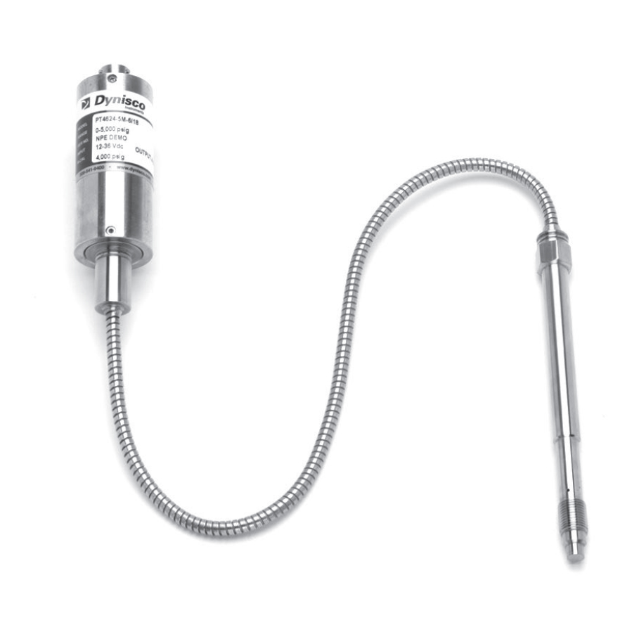
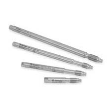
The DYN-X-V transmitters provide the industry standard 0 - 10 Vdc amplified signal designed to work with DCS and PLCs. The DYN-X-V comes equipped with zero and span pots to adapt the transmitter to process conditions. Optional thermocouple or RTD configurations are available to provide melt temperature. The DYN-X-V features a 1/2-20 UNF thread for installation in standard transducer mounting holes and can be supplied with a variety of electrical connections.
⚠ WARNING: This product can expose you to chemicals including mercury and lead, which is known to the State of California to cause cancer and reproductive harm. For more information, go to www.P65Warnings.ca.gov.
From breakthrough technology in the industry’s most complete line of sensors to renowned quality and performance in indicators, controls, and analytical instruments Dynisco has demonstrated the skill, experience and know-how that not only deliver the right solution for your unique application, but also provide unparalleled customer support.
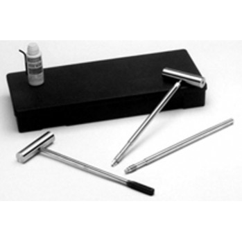
Dynisco Pressure Sensor Care and Maintenance
Learn about the proper care and handling of your Dynisco Pressure Sensors
Dynisco Online Shop Overview
Dynisco’s Online Shop is where you can have access to ordering all Dynisco parts from Polymer Testing Equipment to Sensors to accessories- all to optimize your application.
Dynisco Pressure Sensor Care and Maintenance
In order to maintain your Dynisco pressure sensor's reliability and accuracy over time, certain maintenance and cleaning procedures should be followed. This video focuses on the removal, care, and maintenance process of a Dynisco pressure sensor from an extruder
Sensor Portfolio Overview
At Dynisco, we offer a diverse portfolio of pressure transducers for your unique application. Whether you're looking for industry-leading accuracy and pressure capability, sustainability without sacrificing performance, or reliability on a budget, our sensors can be configured to fit your specific niche.
Understanding Pressure Measurement Needs of Plastic Manufacturing
Divided into 3 sections, obtain a general understanding of pressure transducer basics, the types of plastic extrusion, and the benefits of pressure transducers.
Closed Loop Pressure Control for the Extrusion Process
Extrusion is a continuous process and successful economic production depends on maintaining stable output and melt quality at an accurately controlled rate. Current screw design technology, the use of DC drives, computerized controllers and raw material testing help to deliver the melt to the extrusion die at relatively constant temperature, pressure and viscosity.
Coping with Transducer-Crippling Pressure Spikes
After investigating these spikes, we developed a laboratory method for determining the magnitude of the actual pressure spike that caused a specific field failure. The method shows that pressure spikes many times that of nominal system pressure can occur in a system.
Dynisco Pressure Transducers Relay Vital Information for Closed Loop Control
One of the fastest growing areas for the use of pressure measurement instrumentation is in the co-extrusion of multi layer barrier structures. Many leading co-extrusion design and manufacturing firms, such as the Cloeren Company, engineer melt pressure transducers into their systems for closed loop process control.
Gage vs. Absolute vs. Sealed Pressure
By design, pressure transducers are available to measure gage, absolute or sealed pressure. The most common reference is atmospheric pressure and the units are designated at PSIG. In this case the measuring device is referred to as a Gage Pressure Transducer.
Guide to Pressure Transducer Selection
The purpose of this article is to provide some guidelines for helping a transducer user detect atypical conditions and compensate for them through the proper selection and application of the transducer.
Melt Pressure Measurement: Environmental Effects
The Need For Pressure Measurement in Extrusion In order to maintain the dimensional stability necessary to produce extruded products that meet todays precise quality and tolerance specifications, it is necessary to keep both the output rate and the melt condition constant (1,2). Although it is not possible to measure these quantities continuously, closely related variables such as melt temperature, and constant melt pressure at the die, the output rate can be considered constant.
The Do's and Don'ts of Pressure Transducers
When specifying a pressure transducer for a process measurement, a number of items have to be considered. Some of the more important ones are discussed in terms of the transducer itself as well as the overall measuring system. This information is user-oriented and serves as a practical guide in the selection and application of strain gage pressure transducers.
The Importance of Monitoring Extrusion Stability
It has long been known that pressure instability for polymer melt entering the die usually results directly in ouput variation. Instrumentation used in these early studies was too delicate and expensive to be practical for routine commercial use. An excellent article written by B. H. Maddock, covering some of his early studies is title “Measurement and Analysis of Extruder Stability.”
I'm afraid that I have to respond to your question with a question. Do you want an accurate signal from the transducer during the vacuum part of the process? If so, the answer to the original question is "no"!
If the real question was, "Will the transducer be harmed by a vacuum?", then the answer is "no". Remember a full vacuum is 0 psia or -15 psig. Compared to the full scale range of a transducer of 0-500 psig and probably higher, 15 psi is almost nothing. The transducer will barely notice anything different. The construction of the tip and diaphragm is such that a vacuum causes only a tiny fraction of stresses that it is designed to withstand.
"But suppose," I hear you ask, "I want just an indication of vacuum, not absolute accuracy." Now I must become equivocal. It will probably work. We have performed some testing here, on units from our stock, that indicates a fairly accurate negative output corresponding to increasing vacuum, i.e. output becomes more negative as pressure goes below atmospheric. But this depends on a perfectly filled capillary system. In an ideal world, I would have no qualms about recommending melt pressure transducers for these applications. Since reality is often not ideal and the transducer may not be perfect, a fact we do not like to admit, the output in vacuum may not have the same accuracy as it would for a pressure measurement. Nevertheless, most transducers should give a negative signal in vaccum.
Two caveats - Do not try this with an amplified model such as a 2-wire transmitter. The output cannot go below 4 mA enough to be meaningful. Secondly, if there are significant temperature variations in the process the change in tip temperature could cause a much greater change in output than the vacuum.
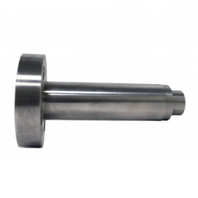
It seems only fair that we discuss the pressure fitting of the general purpose transducers, after a dissertation on the threads of the standard melt pressure models. This should satisfy the equal time requirement.
Providing a good seal in plumbing connections, where system pressures exceed 10,000 psig, presents a significant challenge. O-rings and gaskets may leak. Pipe threads cannot withstand the forces generated by the high pressures. (Please remember that we must test the units to at least 1.5 times rated pressure for our overpressure specification.) Over 50 years ago, NBS (now NIST) developed a design for high pressure fittings that addresses these issues. This cone and thread style was further refined by Autoclave Engineers and others, but most people in our industry refer to the numbering system used by AE. (In "F250C" the "F" means a female fitting and "250" designates its use for 1/4 inch heavy wall tubing.)
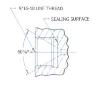
As you can see in the above sketch, the high pressure fitting eliminates the need for sealing material by substituting a small diameter 60° cone as a metal to metal seat. By subjecting the pressure to a limited area, the forces that must be held by the threads is reduced to acceptable levels


38 Forge Parkway,
Franklin MA 02038
+1 508 541 9400
Pfaffenstr. 21, 74078,
Heilbronn, Germany
+49 7131 297 0
Lot 3615, Jalan SM 6/8
32040 Seri Manjung, Perak, Malaysia
+605 6884014


.jpg)
.jpg)