Industries

Applications

Cookie Consent
Cookies are used for statistical purposes and to improve the site.
Cookies will be used after you click "Accept" or if you continue using Dynisco.com
To find out more please review our Privacy Policy.

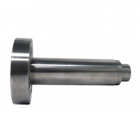
The PT4654XL transmitter provides the industry standard 4 - 20 mA amplified signal to data acquisition or SPC/SQC programs. The PT4654XL comes equipped with adjustable zero and span pots. The PT4654XL features a 1/2-20 UNF jam nut for simple and easy installation in space restricted areas. The transmitter can be supplied in a variety of lengths to meet the requirements of the application.
⚠ WARNING: This product can expose you to chemicals including mercury and lead, which is known to the State of California to cause cancer and reproductive harm. For more information, go to www.P65Warnings.ca.gov.
From breakthrough technology in the industry’s most complete line of sensors to renowned quality and performance in indicators, controls, and analytical instruments Dynisco has demonstrated the skill, experience and know-how that not only deliver the right solution for your unique application, but also provide unparalleled customer support.
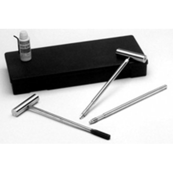
Dynisco Pressure Sensor Care and Maintenance
Learn about the proper care and handling of your Dynisco Pressure Sensors
Dynisco Online Shop Overview
Dynisco’s Online Shop is where you can have access to ordering all Dynisco parts from Polymer Testing Equipment to Sensors to accessories- all to optimize your application.
Dynisco Pressure Sensor Care and Maintenance
In order to maintain your Dynisco pressure sensor's reliability and accuracy over time, certain maintenance and cleaning procedures should be followed. This video focuses on the removal, care, and maintenance process of a Dynisco pressure sensor from an extruder
Sensor Portfolio Overview
At Dynisco, we offer a diverse portfolio of pressure transducers for your unique application. Whether you're looking for industry-leading accuracy and pressure capability, sustainability without sacrificing performance, or reliability on a budget, our sensors can be configured to fit your specific niche.
Understanding Pressure Measurement Needs of Plastic Manufacturing
Divided into 3 sections, obtain a general understanding of pressure transducer basics, the types of plastic extrusion, and the benefits of pressure transducers.
Dynisco traditionally recommends a well regulated 10 VDC power supply as excitation for most (unamplified) models of pressure transducers. We use 10 VDC excitation for our in-process and final testing and in most of the instrumentation that we sell. However a lower voltage source is acceptable and, in fact, one could make the case that it is better for the transducer as there would be less self-heating of the strain gages. It should be noted that using a different excitation voltage may result in a slightly different zero output than that recorded on the final calibration data, but there is no deleterious effect on performance.
Remember that the full scale sensitivity of the transducer is a function of the input (as well as pressure) - 3.3 mV/V (millivolts per volt of excitation). That means that with 10 VDC input the output, at full scale pressure, will be 33 mV, but when you use your 5 VDC excitation, the full scale output will be 16.5 mV. Assuming that your instrumentation is able to cope with this signal level, you have no problem.
The maximum limit of 12 volts is real and should not be exceeded. Higher voltages will cause heating in the strain gages which may result in excess hysterisis, unstable output and longer warm-up time.
The especially perceptive may note that the maximum voltage specified for the general purpose transducers is 15 VDC. The higher limit is allowable on the non-melt pressure transducers for a couple reasons. These models have larger sensing diaphragms allowing the use of larger strain gages which have lower power densities resulting in less self-heating at a given excitation voltage. Also, the application of the melt pressure models is usually in areas with higher ambient temperatures, so the specifications are more conservative to compensate.
I'm afraid that I have to respond to your question with a question. Do you want an accurate signal from the transducer during the vacuum part of the process? If so, the answer to the original question is "no"!
If the real question was, "Will the transducer be harmed by a vacuum?", then the answer is "no". Remember a full vacuum is 0 psia or -15 psig. Compared to the full scale range of a transducer of 0-500 psig and probably higher, 15 psi is almost nothing. The transducer will barely notice anything different. The construction of the tip and diaphragm is such that a vacuum causes only a tiny fraction of stresses that it is designed to withstand.
"But suppose," I hear you ask, "I want just an indication of vacuum, not absolute accuracy." Now I must become equivocal. It will probably work. We have performed some testing here, on units from our stock, that indicates a fairly accurate negative output corresponding to increasing vacuum, i.e. output becomes more negative as pressure goes below atmospheric. But this depends on a perfectly filled capillary system. In an ideal world, I would have no qualms about recommending melt pressure transducers for these applications. Since reality is often not ideal and the transducer may not be perfect, a fact we do not like to admit, the output in vacuum may not have the same accuracy as it would for a pressure measurement. Nevertheless, most transducers should give a negative signal in vaccum.
Two caveats - Do not try this with an amplified model such as a 2-wire transmitter. The output cannot go below 4 mA enough to be meaningful. Secondly, if there are significant temperature variations in the process the change in tip temperature could cause a much greater change in output than the vacuum.
It seems only fair that we discuss the pressure fitting of the general purpose transducers, after a dissertation on the threads of the standard melt pressure models. This should satisfy the equal time requirement.
Providing a good seal in plumbing connections, where system pressures exceed 10,000 psig, presents a significant challenge. O-rings and gaskets may leak. Pipe threads cannot withstand the forces generated by the high pressures. (Please remember that we must test the units to at least 1.5 times rated pressure for our overpressure specification.) Over 50 years ago, NBS (now NIST) developed a design for high pressure fittings that addresses these issues. This cone and thread style was further refined by Autoclave Engineers and others, but most people in our industry refer to the numbering system used by AE. (In "F250C" the "F" means a female fitting and "250" designates its use for 1/4 inch heavy wall tubing.)
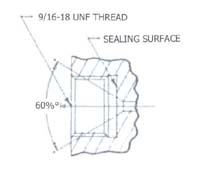
As you can see in the above sketch, the high pressure fitting eliminates the need for sealing material by substituting a small diameter 60° cone as a metal to metal seat. By subjecting the pressure to a limited area, the forces that must be held by the threads is reduced to acceptable levels


38 Forge Parkway,
Franklin MA 02038
+1 508 541 9400
Pfaffenstr. 21, 74078,
Heilbronn, Germany
+49 7131 297 0
Lot 3615, Jalan SM 6/8
32040 Seri Manjung, Perak, Malaysia
+605 6884014
.jpg)